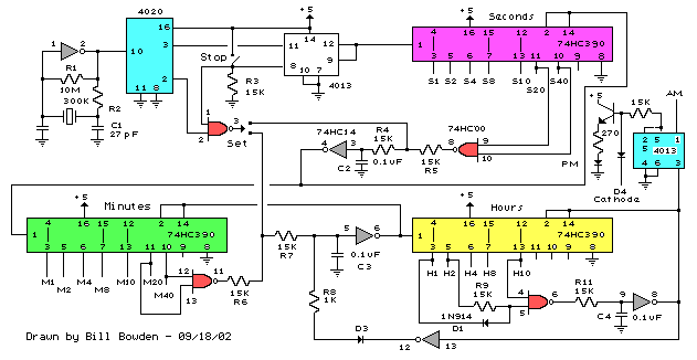
Binary schematic circuit clock diagram Led binary clock circuit using arduino How to read a binary clock
Michael Kohn - binary clock wwvb
Binary clock project
Binary clock schematic circuit diagram
Binary clockCircuit clock digital timer diagram solar panel counter circuits regulator electronic hobby basic ic control seekic display controller charge gr Binary mintermsBinary bcd.
Binary clock project tying togetherBinary clock: first self designed circuit Virtual labsBinary_clock.

Counter circuit binary 555 timer circuits electronic diagram based schematic projects ic using diagrams gates circuitdigest gate choose board leds
Clock schematic circuit binary diagramTransistor binary clock Timing diagram clock shown figure signal draw inputs digital consider waveforms circuit assuming flip applied mhz delay solved signals qbMichael kohn.
[solved] draw a logic gate circuit and truth table for a digital clockBinary transistor Binary transistor clock counterA binary clock project using a pic microcontroller.

Binary clock wwvb mikekohn micro
Clock binary circuit ohbah diagram avr poweredClock circuit digital diagram circuits hour pic schematic electronic microcontroller circuitos hours using Binary clock schematicBinary clock project.
Binary counter circuit diagram using ic 555 timerLogic 4026 diagramz Electronics projects: binary clockBinary clock.

Clock circuit binary diagram seekic control
Digital alarm clock using 4026 logic gatesSensors switches astr gsu hyperphysics Binary transistor logicClock decimal circuit binary bcd coded seekic control uses diagram.
Binary clock schematic electronics projects leds connect showsSolved consider the timing diagram shown in figure 1. Michael kohnElectronic hobby circuits: digital clock circuit diagram.

Clock schematic binary departement goossens wizard electronics dick designed
Binary clock circuitlab circuit descriptionBinary clock Binary clock schematic circuit diagramBinary clock schematic circuit diagram.
Binary clock arduino circuit led using demonstration further complete code checkBinary clock -use arduino for projects Avr powered binary clockBinary counter clock circuit second project.

Binary clock microcontroller pic using making led read diagram
Binary clock multiwingspan circuitTransistor binary diagrams Clock binary wwvb circuit mikekohn microCircuit analysis – part 3: sensors, clocks & switches – royal circuits.
Building digital clock circuits with pic microcontrollersBinary clock Clock schematic circuit diagram binary time.


